News
Wind profile characterization
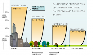
 In an earlier article on wind exposure, we highlighted the different upwind exposure categories defined in ASCE/SEI 7-10 (Minimum Design Loads for Buildings and Other Structures). Exposure categories B, C, and D represent suburban and wooded areas; open, lightly vegetated terrain; and water, salt flats, and ice, respectively.
Of course, reality rarely falls so neatly into predefined categories. Topography, vegetation, and waterways punctuate the land, and buildings, utility plants, roadways, and landfills make humankind’s mark on the earth. Engineers and designers can estimate the effects of relatively simple features by using something as simple as a suitable correction factor. But more complex situations often require a more sophisticated approach to more faithfully represent a site’s wind environment.
Directional variation
The first way to improve our understanding of a site’s wind environment is to slice it up like a pie (with the building at the center), each piece of which represents a wind approach direction. ASCE/SEI 7-10 offers directional procedures that allow engineers to apply the B, C, and D exposure categories to each piece of the pie, angle by angle.
The designer must study the upwind exposure within a 45° angle of the wind direction of interest. So, if one is interested in, say, wind from due north, then the upwind areas contained within angles of ±22.5° are important. If the 22.5° piece of the pie to the west of north is Exposure C and the 22.5° piece of the pie to the east is Exposure B, then that wind direction must use the worst of the two cases, Exposure C.
A more robust solution is to model the upwind exposure, including topography, structures, and other considerations in a wind tunnel test and to measure the approach flow directly. This method offers engineers a very fine-grained picture of the local wind environment. At CPP, we routinely perform such studies in 10° increments, such that a site may have up to 36 unique approach flow profiles.
Special wind climates

When we’re tasked with studying a building that’s located in a particularly complex wind environment, like Hong Kong, it’s not unusual for us to run two studies.
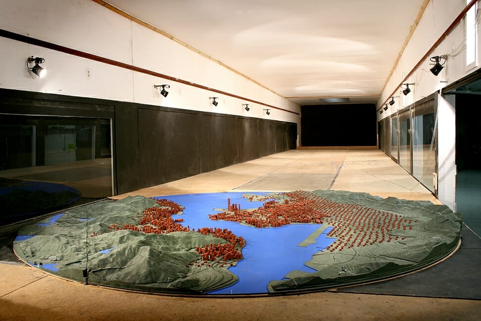
- A topographical study is conducted at a very small scale, up to 1:5,000, to characterize how the surrounding terrain changes the approach flow at the site of interest. We measure wind characteristics for up to 36 different approach angles (every 10°), and those measurements are taken at the site of the proposed building.
- The model study, which is usually performed at a scale of 1:300 to 1:500 is conducted using approach flows that have been specially designed from the results of the first study. Each 10° azimuth is outfitted with the right upstream features in our wind tunnel to recreate the profile that we measured in the topographical study.
It’s a complex procedure, but when you need a reliable, accurate simulation of a building’s wind environment, cutting corners just isn’t an option. This two-part simulation is common for our Hong Kong projects, where mountains, harbours, and a skyline filled with some of the world’s tallest buildings makes a straightforward approach virtually impossible.
