News
How physical modeling can save you money (and possibly your project, too)
Myriad federal, state, and local air quality regulations exist in the United States to keep our population healthy and our air clean. To comply with these regulations, owners and operators of the largest sources of pollution may need to apply for construction and operating permits from their state and local regulatory agencies. These air permits, and their conditions of issue, are meant to protect public health and the environment. The permitting process also serves to inform applicants of the rules that apply to the permitted equipment.
Demonstrating compliance with air quality regulations usually requires that pollutant concentrations be predicted using dispersion modeling software. If the projected concentrations meet the standards, then a permit may be issued and a project can proceed. However, if pollution estimates surpass established limits, 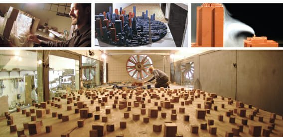 facilities must consider a series of redesigns at best and a dead end project at worst. In many cases, the problem lies not with the design of the facility but with the inputs used to run the dispersion modeling software.
Inputs to the modeling software can be dramatically improved by using wind tunnel techniques. A physical modeling approach lets developers, designers, and engineers ensure that their facilities meet regulatory requirements using the best available science. Such an approach can save time and money—and in many cases, it can even save the project altogether.
Pollution sources and regulatory standards
Regulatory agencies usually classify sources of air pollution into one of three groups.
- Area sources include small sources of pollution like dry cleaners, gas stations, and auto body paint shops.
- Mobile sources include on-road vehicles (g. cars, trucks, and buses) and off-road equipment (e.g. ships, airplanes, agricultural machinery, and construction equipment).
- Point sources include stationary facilities and processes that emit air pollution during manufacturing, power generation, heating, incineration, or other activity. Major point sources include power plants, refineries, chemical plants, municipal waste incinerators, and steel mills.
Any equipment that emits air contaminants from a stationary source (e.g., power plants, factories, and laboratories) must comply with air quality regulations, but exemptions sometimes apply to insignificant sources of air pollution.
Air quality regulations limit the release of air contaminants with the purpose of attaining and complying with the National Ambient Air Quality Standards (NAAQS). The United States Environmental Protection Agency (EPA) defines NAAQS standards for six air contaminants:
- Ozone (O)
- Particulate matter (PM10 and PM5)
- Sulfur dioxide (SO2)
- Nitrogen dioxide (NO2)
- Lead (Pb)
- Carbon monoxide (CO)
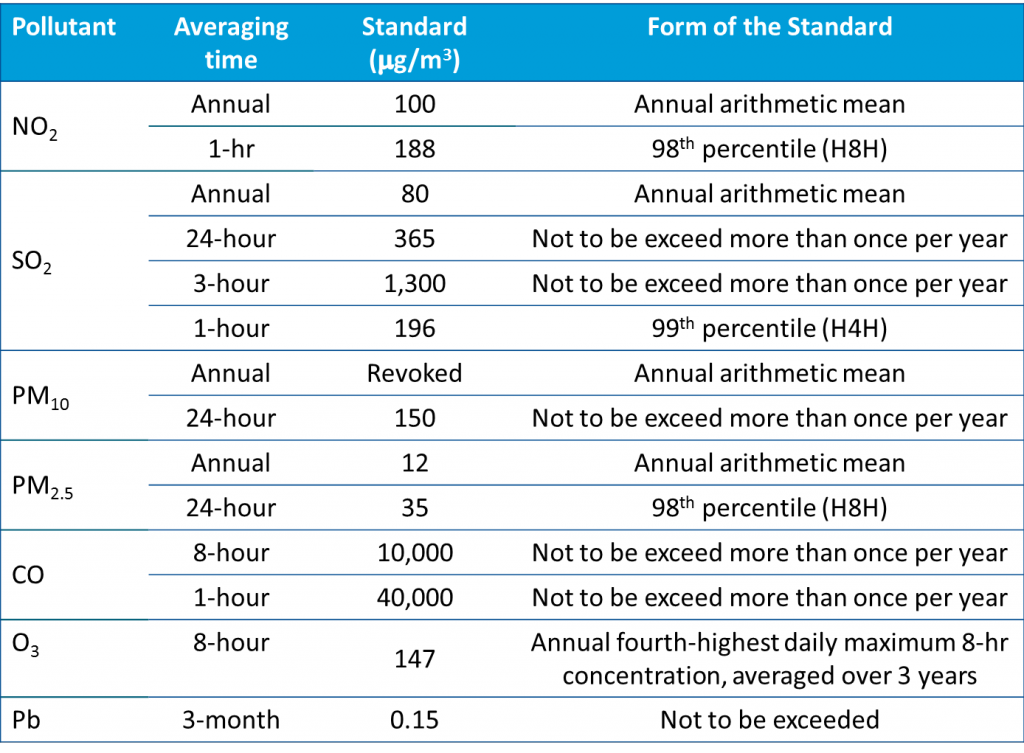
Human health and the environment can suffer when concentrations of these pollutants exceed (or fail to attain) the standard. Table 1 below indicates the specific details of the NAAQS for each of the six regulated pollutants.
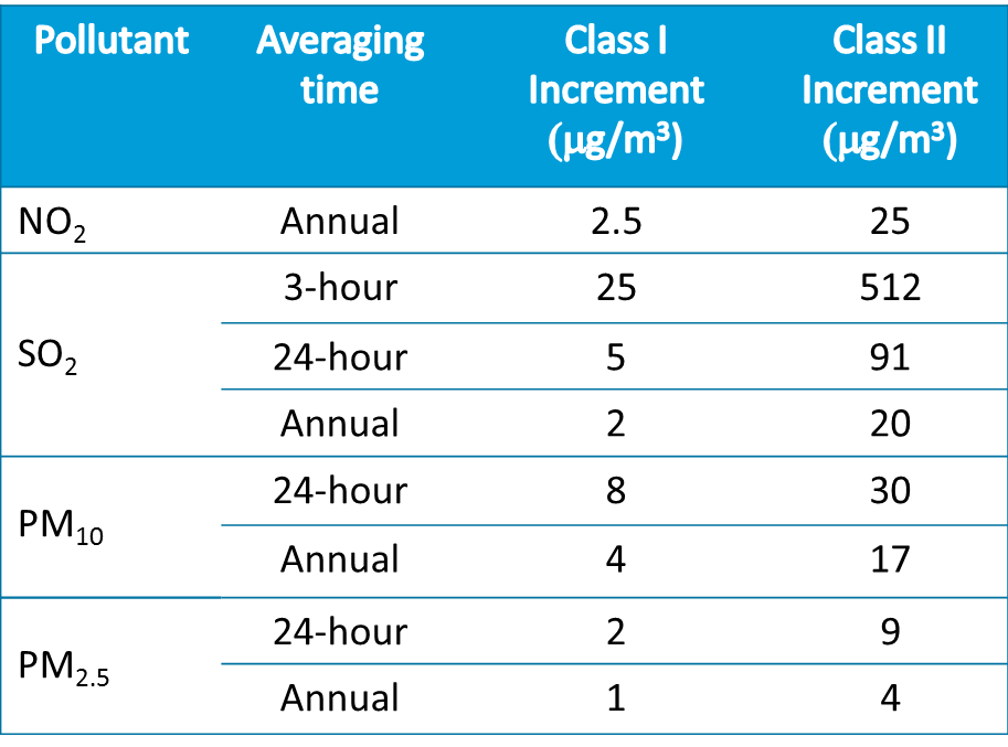
Additional Prevention of Significant Deterioration (PSD) increment standards established by the Clean Air Act limit how much air pollution is allowed to increase in a given geographic area. These standards are meant to keep “clean” and NAAQS-compliant areas from significantly deteriorating. Under the PSD permitting program, new and modified major sources of air pollution must be analyzed with dispersion modeling. This program is reserved for the largest sources of air pollution and applies to all pollutants, even those that do not exceed the NAAQS in an area. The PSD increment standards are given in Table 2.
Normally, compliance with the NAAQS and PSD increment is reserved for (1) new industrial sources with potential emissions above PSD thresholds and (2) existing major sources with projects that have potential emissions above the significant emission rates.[1] However, state and local regulatory agencies may exercise discretion in requiring NAAQS compliance for smaller emission sources. In either case, dispersion modeling is the usual approach to demonstrate compliance.
The EPA’s preferred model for regulatory purposes is AERMOD, but demonstrating compliance with the NAAQS using AERMOD is often easier said than done. This is because traditional numerical modeling techniques, which are inherently conservative, often overstate concentration estimates: Each individual conservative assumption acts cumulatively. However, cutting-edge modeling techniques reduce the effects of so many conservative assumptions to a reasonable level.[2] As with many new techniques, regulatory agencies’ need to evaluate them on a case-by-case basis currently limits their widespread use, but CPP has successfully employed this novel approach with numerous clients.
Components of AERMOD
AERMOD is described as “a steady-state plume model that incorporates air dispersion based on planetary boundary layer turbulence structure and scaling concepts, including treatment of both surface and elevated sources, and both simple and complex terrain.” More simply stated, AERMOD simulates how pollutants disperse from their source to the surrounding area.
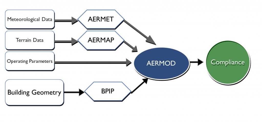
The basic inputs to AERMOD are as follows:
- Meteorological data for the site, which are processed in AERMET to convert them to a standard format that AERMOD can use
- Topographic data for the site and its surroundings, which are processed in AERMAP to assign terrain elevations to receptors, emission sources, and buildings in the modeling domain
- The building geometry of the proposed facility, which is processed in the Building Profile Input Program (BPIP) by (1) using various logical assumptions to specify length, width, and height (L–W–H) of the predominant building structures and (2) calculating the building dimensions that AERMOD requires for running its dispersion simulation
- Finally, the AERMOD package itself is executed using stack and operating parameters such as emission rate, stack height, temperature, and flow rate
AERMOD’s results are only as reliable as the inputs and assumptions used to create them: garbage in, garbage out. Any inaccuracy or conservatism in the preprocessors (AERMET, AERMAP, and BPIP) or in the user-specified runtime parameters propagate and snowball through AERMOD’s calculations and affect the final result. This is a key problem in regulatory modeling since unreasonable assumptions can predict very high concentration estimates.
Limitations of BPIP-PRIME
One of AERMOD’s most obscure features concerns how it accounts for building downwash. Downwash effects in AERMOD are captured using BPIP and the Plume Rise Model Enhancements (PRIME) equations and formulas. BPIP relies upon user-specified building plan dimensions and tier heights, along with various logical assumptions from past research, to specify a single length-width-height (L–W–H) and building location for each of 36 wind directions.
Building shape, in particular, presents special challenges for AERMOD. This is because AERMOD and the BPIP preprocessor assume simple, box structures. AERMOD frequently overestimates pollutant concentrations for such structures as the following.
- Short, wide, and long buildings
- Wide and narrow buildings
- Lattice structures
- Streamlined structures
In establishing dimensions, BPIP assumes that lattice, porous, and streamlined structures are rectangular solids, which is a conservative assumption that overstates downwash effects, as illustrated in Figure 2 below. Furthermore, BPIP often merges separate buildings into one large building and may overestimate the effective building height by using only the tallest tier. The net result is that, in some situations, BPIP generates building dimensions that conflict with the theory used to develop PRIME.
These BPIP-generated building dimensions are used by AERMOD’s PRIME algorithm to estimate plume growth and restricted plume rise for plumes affected by building wakes. The downwash effect, in turn, is based on algorithms from streamlines obtained from wind tunnel testing of a limited set of building dimensions. However, when building dimensions lie outside of the range of the tested parameters, the theory no longer applies, yielding unrealistic and excessive concentrations near ground level (e.g., at fence lines).
Despite these limitations, use of BPIP-generated building dimensions is widespread and is considered the conventional approach, even in such situations for which BPIP is known to be inadequate. In such cases, unreliable building dimensions dramatically overestimate building downwash effects and yield unrealistically high concentration estimates. Such inaccurate results may prompt facilities to spend substantial sums of money on such unnecessary strategies as increasing stack heights and installing expensive control systems. The most onerous overestimates can even stop a project in its tracks.
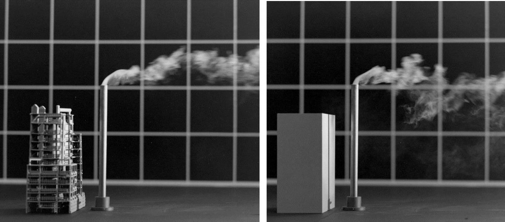
Physical modeling and Equivalent Building Dimensions (EBD)
Physical modeling is an effective alternative that can refine AERMOD’s inputs and deliver more accurate results. The first step in deciding whether or not BPIP is overestimating downwash effects is to review the output from BPIP, a diagnostic step that most consultants overlook. However, taking the time to do this can shed light on unreasonably high results.
Figure 3 shows results from CPP’s proprietary BPIP diagnostic tool, which identifies problematic wind directions and estimates the degree to which AERMOD over-predicts pollutant concentrations. If a BPIP output file suggests that downwash is causing unrealistic results, a physical modeling approach can correct inaccurate building dimensions and lead to more accurate estimates.
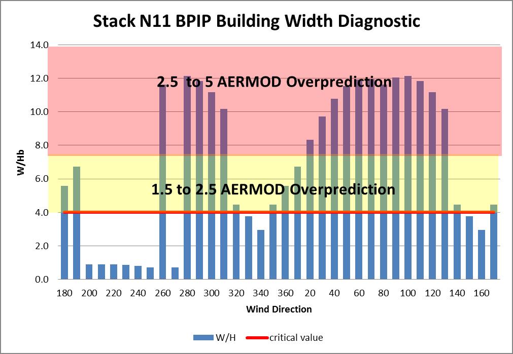
Physical modeling is well-suited to cases that feature problematic building downwash effects. With technology’s continued march, it is possible—likely, even—that numerical methods will one day favorably compare to physical modeling. At present, however, the wind tunnel remains the best available scientific tool for studying fluid dynamics in complex environments, including wind flow patterns around buildings and structures.
A simple and effective way to improve AERMOD’s performance when BPIP output is inadequate is to find Equivalent Building Dimensions, or EBDs. EBDs are determined using the benefits of physical modeling with a wind tunnel approach. This approach includes:
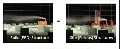
Using a scale model of the real buildings, surroundings, and terrain to quantify and characterize dispersion behavior for wind approaching from all directions.A simple and effective way to improve AERMOD’s performance when BPIP output is inadequate is to find Equivalent Building Dimensions, or EBDs. EBDs are determined using the benefits of physical modeling with a wind tunnel approach. This approach includes:
- Replacing the scale model with a simple rectangular building and moving it to various locations near the pollution source (stack).
- Adjusting the model’s size, shape, and position until the dispersion behavior at ground level matches that observed for the scale model.
Once the appropriate ground behavior has been identified, the simpler rectangular building can be considered a structure having equivalent building dimensions (EBDs). These dimensions may then be passed directly to AERMOD, bypassing the approximations and simplifications that make BPIP so conservative and unrealistic.
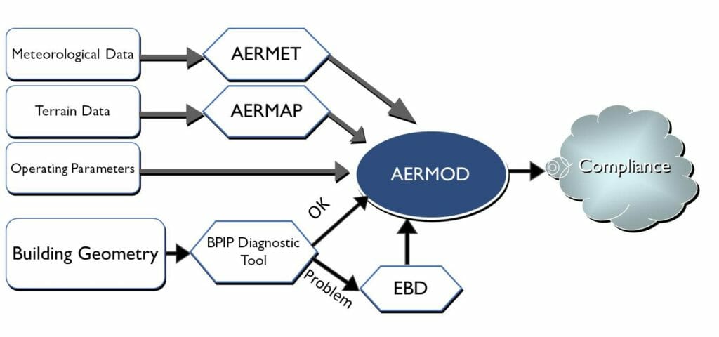
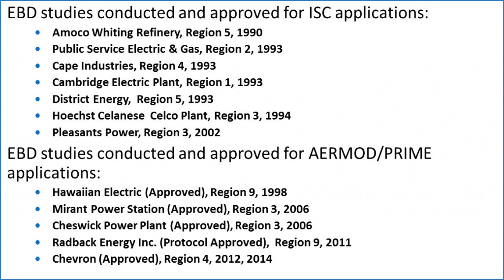
The EBD approach not only saves time and money, it also delivers more accurate results than would otherwise be available. For over two decades the benefits of physical modeling have been used in regulatory modeling to refine the building dimensions of buildings and structures that fall beyond the applicability of numerical models like PRIME, as shown in Figure 6 below.
EBD Validation Study
An evaluation study was conducted at Mirant’s Potomac River Power Plant in Alexandria, Virginia. A wind tunnel study determined appropriate Equivalent Building Dimensions (EBDs), which were passed to AERMOD, along with meteorological data appropriate for the site. The resulting downwind concentrations patterns were nearly identical to those observed in the wind tunnel, confirming that the wind tunnel data created suitable inputs to AERMOD.
Additionally, a network of six sulfur dioxide (SO2) monitors were installed on a nearby high-rise tower (Marina Towers) from June 1st to November 30th of 2006 to evaluate model performance. The results from this validation study demonstrated that AERMOD run with EBD inputs (AERMOD/EBD) produced values that were about half of those obtained by using BPIP generated building dimensions. Nevertheless, AERMOD/EBD still over-predicted concentrations by more than a factor of two, indicating that the method still includes conservatism. You can learn more about the Mirant project here.
Physical modeling can justify tall exhaust stacks
According to the Code of Federal Regulations (Title 40, Section 51.110 (ii)), the Good Engineering Practice (GEP) stack height is defined as the greater of the following:
- 65 meters
- 5H (for stacks in existence in January 12, 1979), or H + 1.5L (for all other stacks), where H is the height of the building itself or any significant nearby structure or structures and L is the lesser of the projected height or width of the building in question, or
- The height determined by a wind tunnel modeling study.
The first criterion simply establishes a minimum stack height, and the second is a generic method that can’t possibly cover every situation.
It is commonly misunderstood that the GEP stack height is limited to 65 meters or 2.5 times the height of the building (options 1 and 2 above), but this is not the case. Depending on the surroundings and the details of the project, a wind tunnel test can justify heights well above the formula or, in some cases, show that the higher stack is not actually needed for compliance.
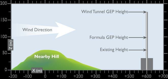
For example, Figure 7 below illustrates how terrain can affect the GEP stack height. In the depicted case, raising the stack only to the formula height would be insufficient because it lies in the wake of the adjacent hill. However, wind tunnel testing demonstrates that a much higher stack can exhaust pollutants well above the wake. The GEP stack formula alone cannot capture such effects.
Conclusion
Physical modeling is the most accurate way to determine building dimensions and GEP stack heights for regulatory permitting. Wind tunnel testing is built upon the best available science to replicate the complex wind dynamics of structures and terrain at a given site. In many cases, physical modeling with a wind tunnel approach can demonstrate NAAQS compliance even when other methods fail.
Put CPP’s expertise to work for you. CPP is pleased to offer a one stop shop for modeling and permitting. Vice President Dr. Ron Petersen and Senior Environmental Engineer Dr. Sergio Guerra bring a wealth of expertise in physical modeling, numerical modeling, and regulatory permitting to our clients. Our air quality experts deliver more accurate results, saving you time, money, and frustration.
Understanding the regulatory requirements is hard enough. Our air quality and environmental experts can assess your best strategy to navigate the complex air permitting process. Contact CPP today to learn how to keep your project on track and on budget.
